Skip to content

Expertise

Electric motor design
and development.

I design electric motors and work on motors that need to perform better. That can mean choosing a motor and gearbox, reducing winding temperatures, tuning the current regulator, or finding out why the dyno results disagree with the model.

Defining the machine

Machine architecture

Choosing between an existing motor, a custom design, and different motor-and-gearbox combinations.
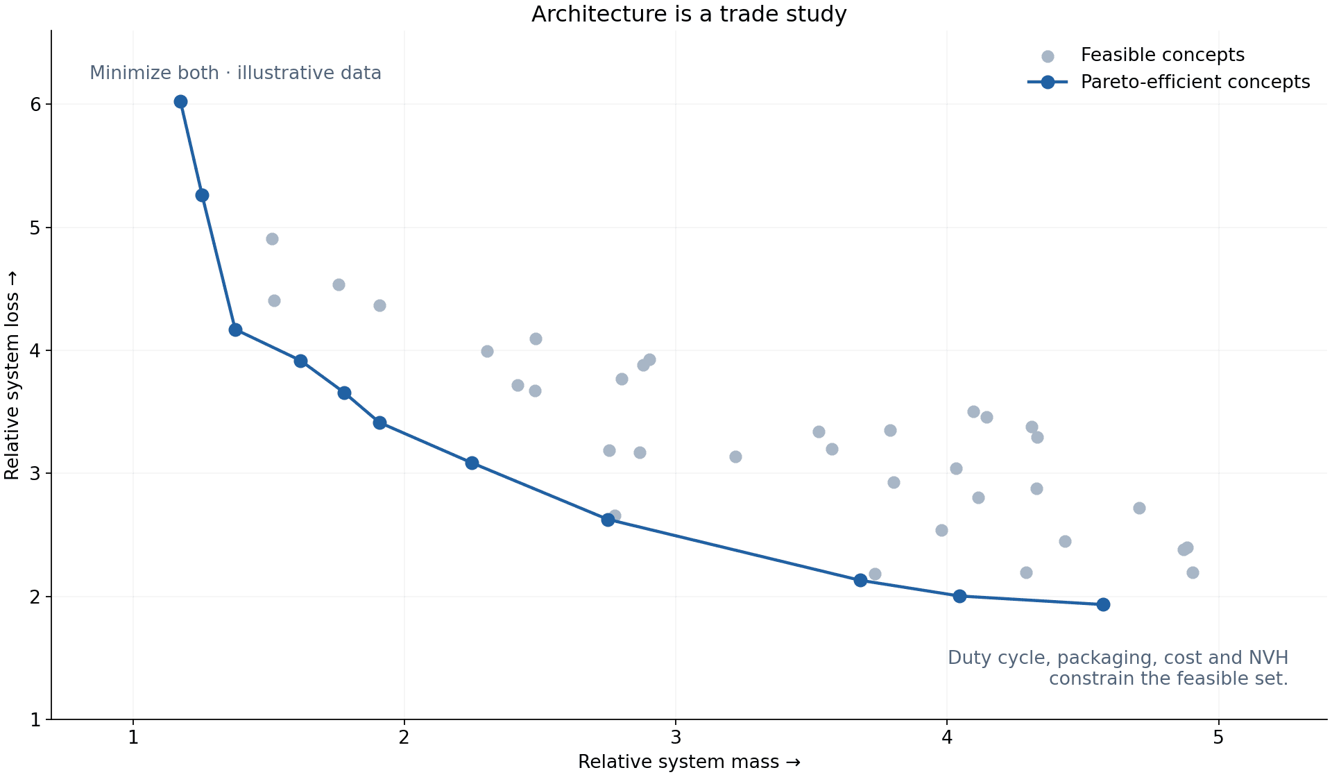
Illustrative Pareto front comparing relative system mass and loss, minimizing both
Illustrative trade study; synthetic concepts, not a product optimization result.

Does this application need a custom motor?

  • Does an electric motor make sense for the customer need, and could an off-the-shelf solution meet the immediate requirement?
  • Axial or radial flux? Direct drive or a gearbox? Which trade-offs matter over the actual duty cycle?
  • Would planetary, worm, helical, or spur gearing best fit the package, efficiency, cost, and noise requirements?

How I approach it

I start with the job the motor has to do and check whether an available product can do it. If a custom design is needed, I compare axial and radial flux, direct drive and geared options. Pareto fronts show where reducing mass, loss, or cost requires a compromise elsewhere. Cooling, manufacturing, controls, and noise can rule out an otherwise attractive concept.

What I need to know

Customer need, duty cycle, available products, package, system cost, efficiency targets, and noise requirements.

Application requirements ↔ machine architecture
Developing the design

Electromagnetic design

Magnetic loading, losses, torque production, and the assumptions behind the model.

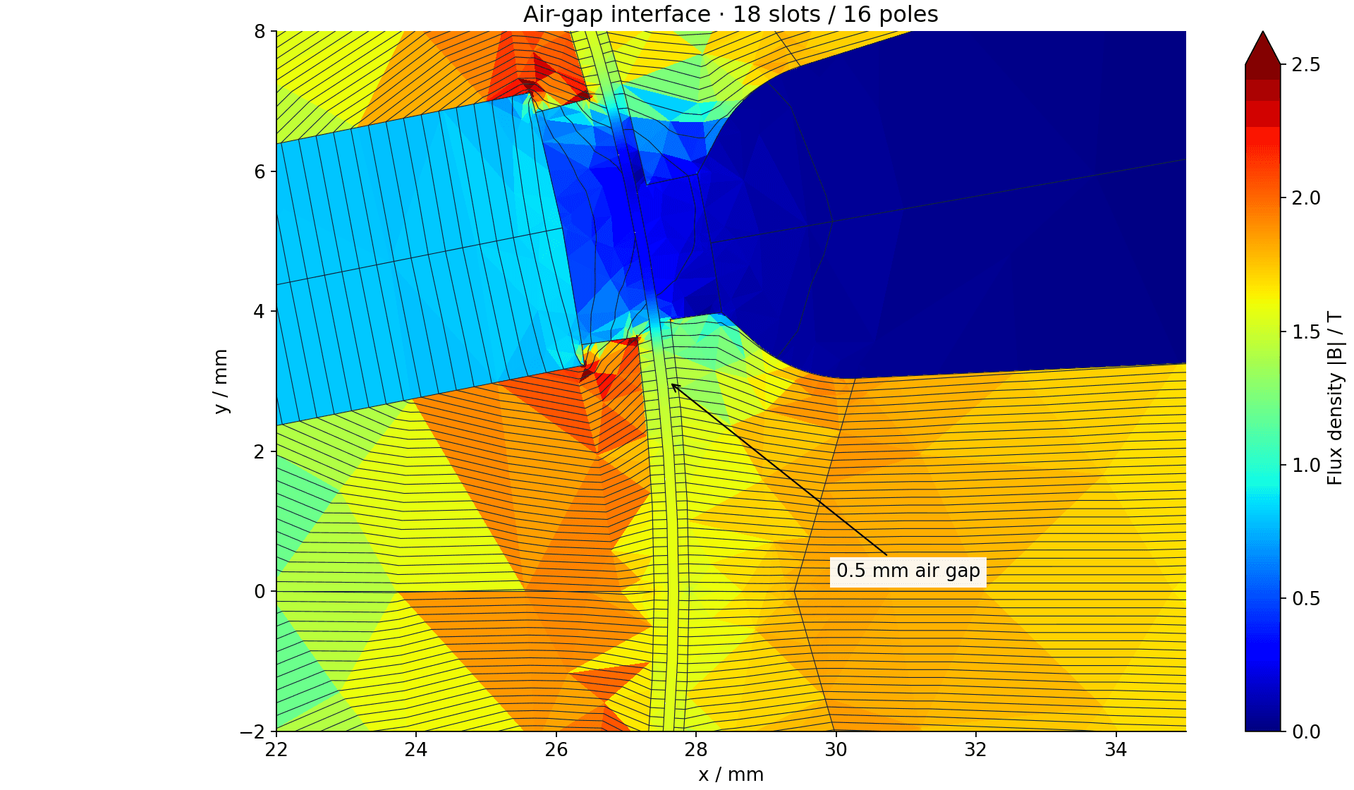
Jet color map of solved FEMM air-gap flux density with flux contours for an 18-slot 16-pole spoke motor
18-slot / 16-pole reference · open-circuit FEMM solution, rendered with the jet colormap.

What is limiting torque or efficiency?

  • Is a torque or efficiency shortfall coming from the magnetic circuit, winding, or operating point?
  • How sensitive is the result to magnet properties, air gap, and local saturation?

How I approach it

I use analytical calculations and FEA to work through the winding, magnets, steel, and air gap. I look for where the steel saturates, how the flux links the winding, and how those results change with current and temperature. The air-gap plot is one view of that work; torque and loss calculations are what we compare with the bench.

What I need to know

Geometry, materials, winding details, operating points, and the performance target that is not being met.

Magnetic circuit ↔ winding ↔ air gap

Connecting the drive

Controls & integration

Current regulation, rotor-angle sensing, inverter limits, and field weakening.

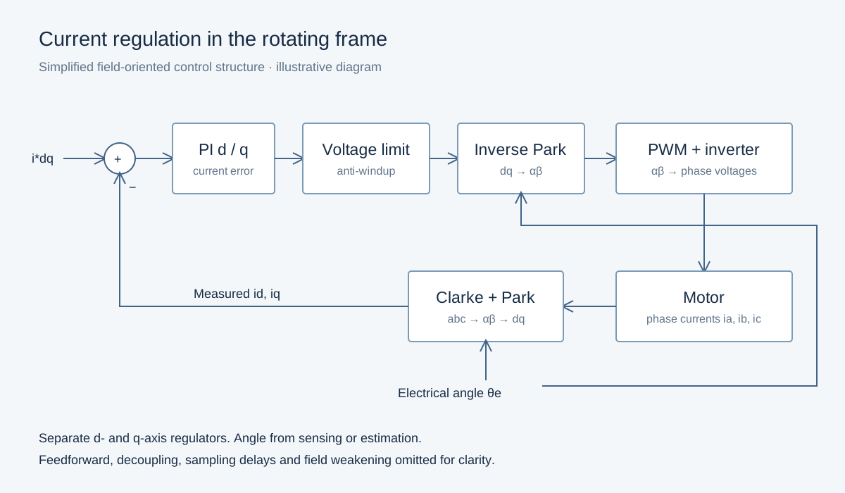
Field-oriented current regulator with Clarke and Park transforms, d and q PI controllers, voltage limiting, PWM inverter and motor feedback
Simplified control structure; separate d/q PI regulators with measured-current feedback.

Do the controls match the motor?

  • Do the control parameters and current-angle strategy match the actual machine?
  • Is the limit in the motor, the inverter, the sensing, or the control implementation?

How I approach it

I check flux linkage and inductance against the parameters in the controller, then work through the d/q current regulators, rotor-angle sensing, voltage limits, and field weakening. A motor can fall short because of its geometry, but also because the drive is applying the wrong current angle or cannot track the requested current.

What I need to know

Motor parameters, inverter and bus limits, control strategy, sensor configuration, and synchronized measurements.

Machine model ↔ inverter ↔ controls

Understanding the duty cycle

Thermal design

Transient loading, winding hot spots, heat paths, and cooling conditions.

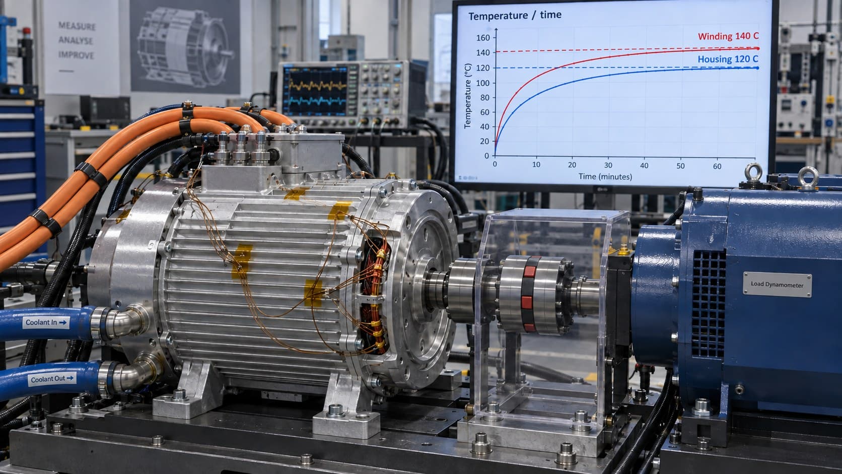
Illustrative motor on a dyno with thermocouple wiring and rising temperature traces on a background monitor
Representative test illustration. 120°C and 140°C are example limits, not specifications or test data.
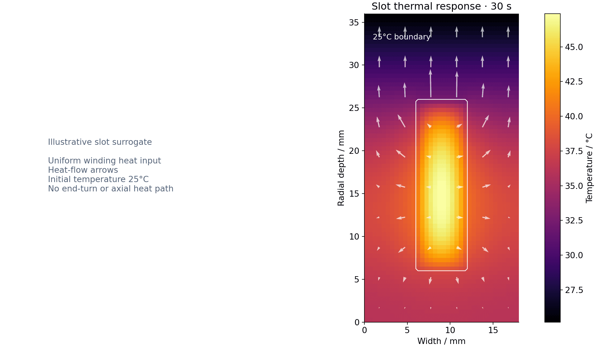
Calculated temperature and heat-flow arrows after 30 seconds in a simplified heated slot
30 s conduction example: simplified slot, 25°C initial and outer boundary, uniform winding heat input. Not a motor-specific thermal prediction.

What sets the thermal limit, and when?

  • What happens in the slot and end turns during a short overload, and what happens after repeated cycles?
  • Are the limits coming from copper loss, a thermal interface, coolant conditions, or the way temperature is measured?

How I approach it

I connect the loss model to the thermal paths and duty cycle, then check those assumptions against an instrumented machine. Slot and end-turn temperatures, sensor placement, contact resistance, and cooling conditions all affect how much confidence to put in a temperature limit.

What I need to know

Loss maps, duty cycle, winding and insulation construction, cooling conditions, sensor locations, and component temperature limits.

Losses ↔ heat paths ↔ temperature ↔ duty cycle

Preparing the hardware

Manufacturing constraints

Adjusting the electromagnetic design to the materials, tolerances, and processes available.

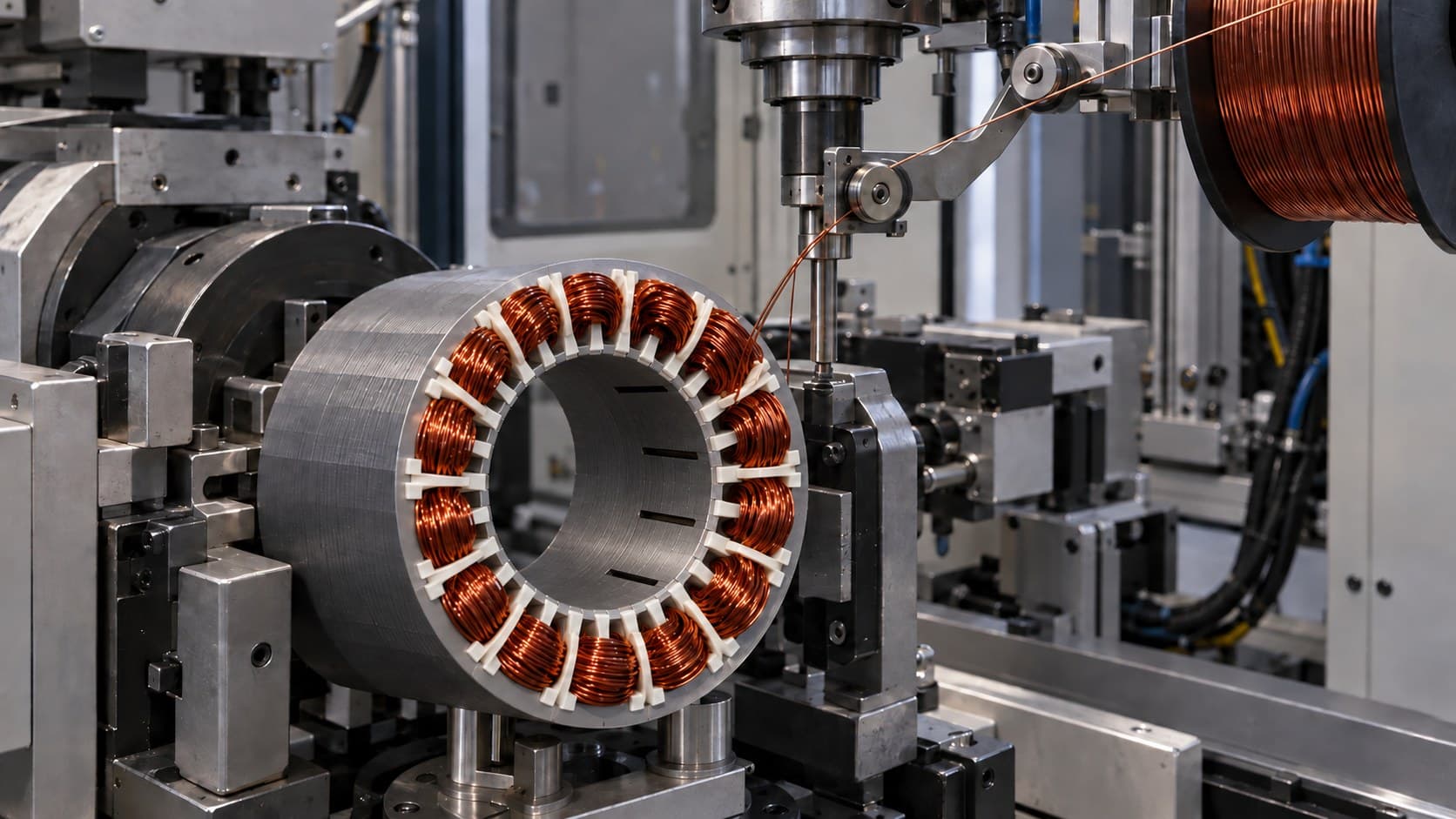
Illustration of automated copper winding equipment around a laminated stator
Representative equipment illustration; not a customer facility.

Can this motor be built consistently?

  • Can the winding be produced consistently with the available automation, slot access, fill factor, and insulation process?
  • What happens when the air gap, magnet position, or stack dimensions vary?
  • Which changes to laminations, retention, or assembly preserve the required performance?

How I approach it

I work through slot access, winding process, insulation, magnet placement, and assembly tolerances with the people building the motor. A winding that fits in the model still has to be inserted, insulated, and retained. I check what each proposed manufacturing change does to torque, losses, and the air gap.

What I need to know

Supplier feedback, tolerance stack, material options, winding process, and assembly or retention constraints.

Electromagnetic geometry ↔ manufactured hardware

Validating or troubleshooting

Test & model correlation

Separating machine behavior, measurement error, thermal conditions, and control effects.

Illustrative instrumented electric motor coupled to a load dynamometer with temperature monitoring
Representative dyno illustration; screen traces are illustrative, not measured results.

Why does the bench disagree with the model?

  • Are the model and test describing the same operating conditions?
  • What measurement would distinguish the possible causes of a performance gap?

How I approach it

I have spent more than 10,000 hours on test benches proving my designs against their models. When results disagree, I check that current, speed, temperature, and rotor angle match the modeled conditions. Then I check the instrumentation and choose a test that can distinguish a motor problem from a controls or measurement problem.

What I need to know

The model, test setup, instrumentation, calibration, operating conditions, and raw measurement data.

Predicted performance ↔ measured behavior

Finding the source

Noise & vibration

Finding the source of motor and gearbox noise, then testing changes to the existing hardware.

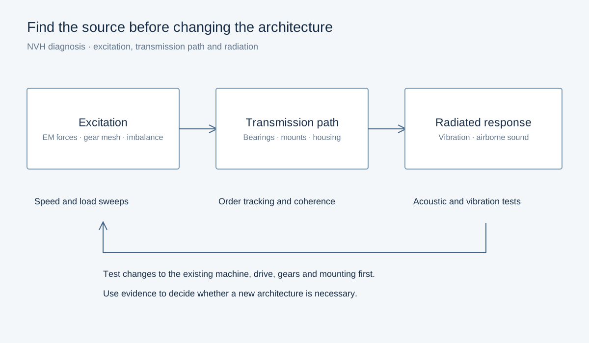
NVH diagnostic diagram showing excitation, transmission path and radiated response with a test feedback loop
Diagnostic framework: establish the source and path before changing architecture.

Where is the noise actually coming from?

  • Is the dominant excitation electromagnetic, switching-related, gear mesh, imbalance, or a bearing effect?
  • What can be made quieter in the existing motor, drive, transmission, or mounting before changing architecture?

How I approach it

I look at how the noise changes with speed, load, and current. Order tracking and synchronized current, vibration, and acoustic measurements help separate motor forces, gear mesh, bearings, and structural resonances. I check whether controls, gears, or mounting changes can quiet the existing design before proposing a new architecture.

What I need to know

Speed and load sweeps, current and vibration recordings, acoustic measurements, gear and bearing details, and mounting conditions.

Excitation ↔ structural response ↔ radiated noise

Tell me about your motor

What does it need to do, and what is getting in the way?

Contact Chad